
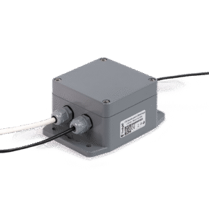
LTE Logger Lite
One 4-20 mA loop, two dry contacts, a 1-Wire bus and a 12 or 24 V sensor supply — the Logger Pro framework in a smaller, battery-only box.
| Qty | 1 pc | 10–99 | 100–499 | 500+ |
|---|---|---|---|---|
| Price | €150.00 | €112.50 | €90.00 | €75.00 |
+ €25 / device / year — findy IoT Platform, global LTE SIM, OTA updates, support.
Each block is a circuit on the R.3 board, not a GPIO you have to build around. Colour indicates type.
Every position below is a 5.0 mm-pitch screw terminal on the R.3 board. Field wiring goes here; nothing else on the board needs a tool.
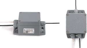
Top view · outline, holes, terminal blocks and connector positions read from the R.3 PCB file; component blocks simplified. Dashed lines are mouse-bite tabs — the side wings with the outer screw holes snap off if the enclosure does not need them.
J5
Sensor supply| 1 | +12 / 24 V | Step-up output through a 0.2 A resettable fuse |
| 2 | GND | |
| 3 | +12 / 24 V | Same rail as pin 1 — two sensors, one fuse |
J13-1
4-20 mA loop| 1 | GND | |
| 2 | −Load | Low side of the 5.1 Ω shunt |
| 3 | +Load | Loop return in · INA180 ×20 → 18-bit ADC |
J19-2
Powered 4-20 mA sensor| 1 | +3.3 V | Switched peripheral rail — on only while measuring |
| 2 | +Load | Same node as J13-1 pin 3 |
| 3 | GND |
J19-1
Dry contact| 1 | GND | |
| 2 | GND | |
| 3 | Digital IN 1 | IO34 · 10 kΩ pull-up to 3.3 V · close to GND · API coming |
J10-1
1-Wire + dry contact| 1 | +3.3 V 1-Wire | Own current-limited switch (SY6280) |
| 2 | 1-Wire data | IO4 · 4.7 kΩ pull-up · API coming |
| 3 | Digital IN 2 | IO14 · 10 kΩ pull-up to 3.3 V · counted by the ULP |
Enclosure, battery, consumption and buffer figures as published on findyiot.com for this logger family; terminal, rail and processor figures read from the R.3 schematic and PCB.
The R.3 board follows the Logger Pro GPIO map almost pin for pin, so last.py written for one runs on the other. The differences are the ones that matter for wiring.
| GPIO | Logger Pro framework | Logger Lite R.3 | Status |
|---|---|---|---|
| 17 · 23 · 21 · 36 · 5 | Modem rail, PWRKEY, UART, DTR | Identical — through a TXS0108E level shifter | ✓ same |
| 19 · 18 | I²C SCL / SDA to ADC at address 104 | MCP3422A0 — address 104 | ✓ same |
| 25 | Peripheral power enable | TPS22919 → 3.3 V peripheral rail → step-up and 1-Wire rails | ✓ same |
| 27 · 15 | Buzzer · reed switch wake-up | PB0540MK buzzer · CT10-2540 reed | ✓ same |
| 14 | Pulse input 2, counted by the ULP | Digital IN 2 — J10-1 pin 3 | ✓ same |
| 4 | Pulse input 1, counted by the ULP | 1-Wire data — J10-1 pin 2, 4.7 kΩ pull-up | ⚠ role differs |
| 34 | — | Digital IN 1 — J19-1 pin 3 | ⚠ no framework parameter yet |
| 12 · 22 | Relay 12 V · relay 5 V | No relays fitted | — not used |
| 16 · 35 | — | Modem PON_TRIG · PSM_IND | ⚠ new on Lite |
measure() with machine.Pin and a custom parameter ID.boot.py and firmware_core.mpy stay as shipped. You edit last.py: what the device measures, what it reports, and how long it sleeps.
# Logger Lite default report — loop current, pulses on IN 2,
# wake-up period and the timestamp of the last successful report.
datalist = ['520', '439', '421', '443']

def start(self):
    self.measure()
    self.report(False, datalist)          # alarm=False
    self.prepareSleep(int(core.db.read('421')), True)  # True = magnet wakes it

fw.start = start
# The loop on J13-1 arrives as mA on ADC channel 1.
# Scaling limits 553–556 are set in the platform, not here.
ina1 = round(self.adcMeasure(b'') / 100, 2) # mA
sensor_min = float(core.db.read('553')) # 4 mA
sensor_max = float(core.db.read('554')) # 20 mA
qty_min = float(core.db.read('555')) # 0 bar
qty_max = float(core.db.read('556')) # 10 bar
qty = (ina1 - sensor_min) * ((qty_max - qty_min) /
(sensor_max - sensor_min))# The 12 / 24 V rail on J5 follows the peripheral rail (IO25).
# Give the transmitter its warm-up time (parameter 587), read, switch off.
import machine, time
periph = machine.Pin(25, machine.Pin.OUT)
def measure(self):
periph.value(1) # 3.3 V + 12/24 V on
time.sleep(int(core.db.read('587'))) # sensor warm-up, s
core.db.write('520', str(self.adcMeasure(b'') / 100))
periph.value(0) # everything off again
fw.measure = measureEvery card below is a system parameter the framework fills in. The loop value is scaled to your engineering unit by the limits you enter in Settings — no code.
4-20 mA · dry-contact sensors
12/24 V rail, warm-up, ULP counting in sleep
LTE Logger Lite
Your measure() runs here — MicroPython v1.25
LTE Cat 1 bis / 2G
Global findy SIM, embedded
findy IoT Platform
Measurements, settings, commands — by parameter ID
Your system
API, webhooks, export
Each one uses the terminals as wired on R.3 and the framework as shipped — no soldering, one file to edit.
Ready-made solutions
Complete deployments built on findy loggers — metering, level and pressure monitoring, environmental sensing — delivered and supported end to end.
View solutionsHave your own system?
We supply the logger and the SIM. You take the data from the platform API into the infrastructure you already run.
Talk to our team →Write your own logic
You're here. Wire the terminals, edit one file, deploy the next version over the air.
Can't do it? Enterprise team →